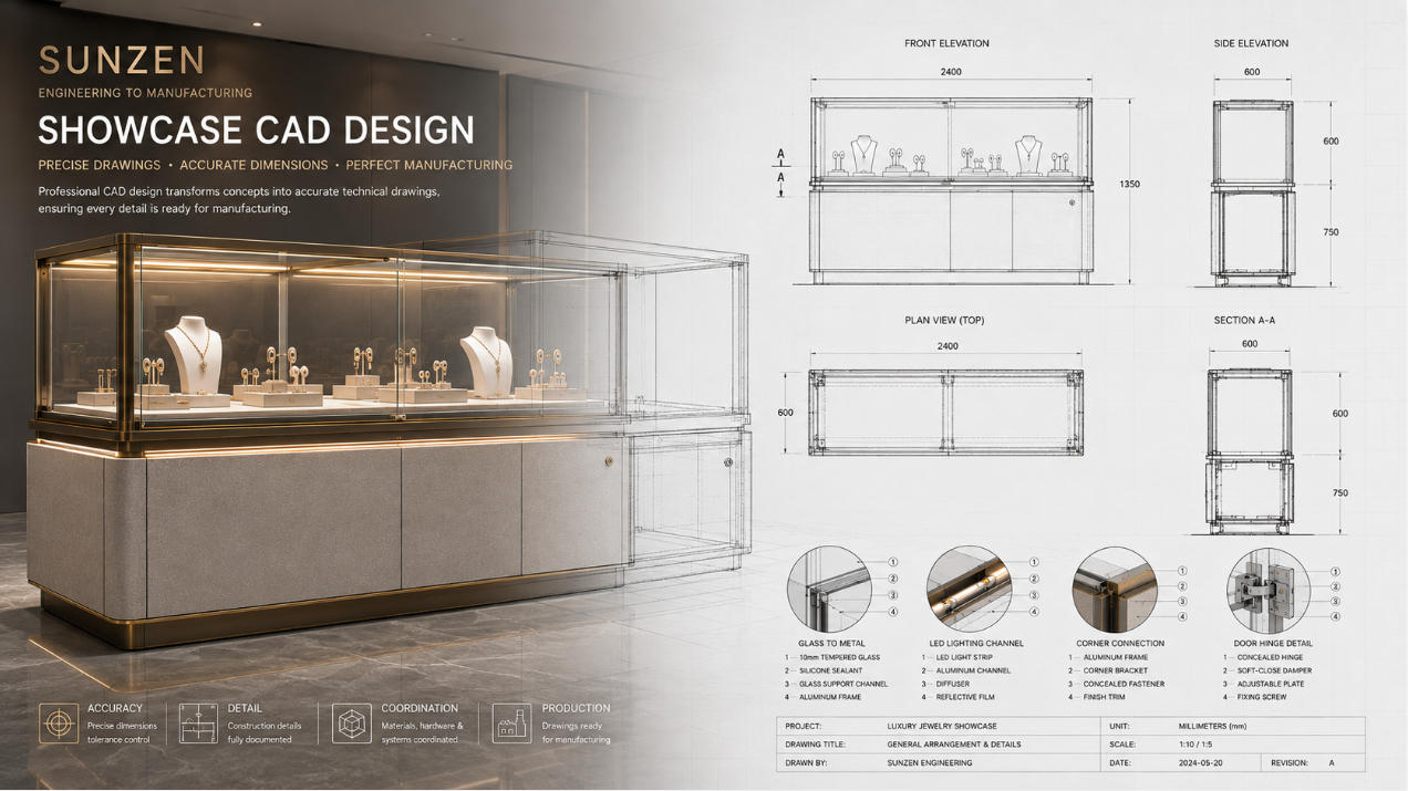
Showcase CAD Design for Custom Display Case Manufacturing
Professional showcase CAD design translates an approved showcase concept into precise technical drawings that communicate dimensions, construction, glass, materials, hardware, lighting and assembly requirements.
A 3D rendering can explain how a showcase should look, but manufacturing requires a different level of information. Front and side elevations, plan views, sections, enlarged details and component dimensions define how the showcase will actually be fabricated and assembled.
SUNZEN develops CAD documentation as part of our showcase engineering process, connecting approved designs with technical development and showcase manufacturing.
What Should a Showcase CAD Drawing Communicate?
Define the Showcase Accurately
Overall dimensions, component sizes, reference levels, openings and critical clearances establish the physical geometry of the showcase.
Explain How Components Connect
Sections and enlarged details communicate relationships between glass, metalwork, cabinetry, shelves, doors and internal supports.
Turn Design Intent into Buildable Information
Technical drawings give engineering and manufacturing teams a common reference for fabrication, assembly and quality inspection.
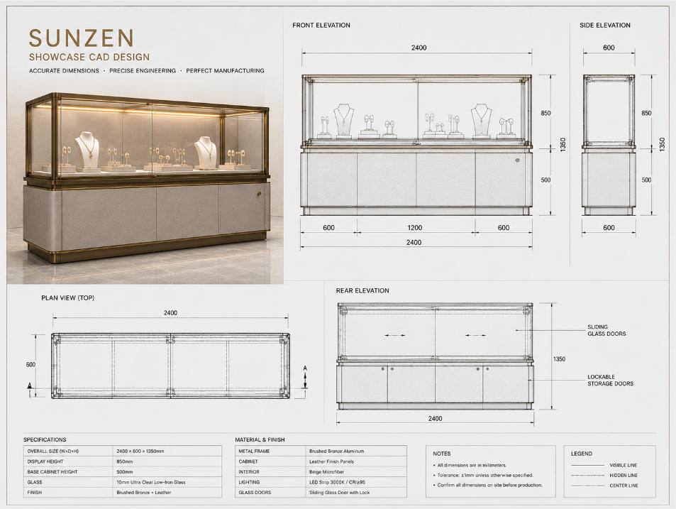
Define the Showcase from Every Principal View
A complete showcase CAD drawing should communicate the geometry of the fixture from the views required to understand its construction.
Front Elevation: Defines overall width, height, doors, drawers, visible divisions and major design relationships.
Side Elevation: Establishes depth, glass profile, base construction and front-to-back relationships.
Plan View: Explains footprint, glass arrangement, structural position and opening relationships from above.
Rear Elevation: Can define staff-side doors, drawers, locks, electrical access and operational components where required.
Reference Dimensions: Connect individual views through consistent levels, centers and dimensional references.
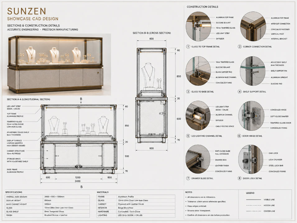
Use Sections to Explain What Elevations Cannot Show
External elevations describe appearance, while sections reveal how the showcase is constructed internally. This makes sectional drawings essential when glass, frames, lighting, doors, shelves and cabinetry interact within a limited space.
Enlarged details can then isolate critical interfaces such as glass-to-metal connections, LED channels, shelf supports, door hardware, drawer systems and base construction.
The objective is not to add detail for its own sake. Technical information should clarify the areas where fabrication or assembly could otherwise be interpreted incorrectly.
Dimension the Showcase for Fabrication and Assembly
Overall Dimensions
Define the external width, depth and height required to coordinate the fixture with the project space.
Component Dimensions
Identify the sizes of glass, frames, panels, drawers, doors, shelves and other important fabricated components.
Clearances & Gaps
Control moving components, door openings, drawer travel and visible joints through appropriate dimensional relationships.
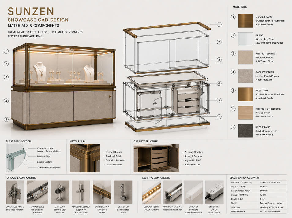
Connect CAD Geometry with Material and Component Specifications
A technical drawing should identify more than shape and size. The drawing set also needs to communicate which materials and components correspond to the geometry being shown.
Glass: Identify panel location, dimensions and relevant glazing relationships.
Metalwork: Define frames, trims, brackets, channels and structural components.
Cabinetry: Coordinate panels, doors, drawers, internal structure and decorative finishes.
Hardware: Locate hinges, slides, locks, handles and shelf supports.
Lighting: Identify LED profiles, channels and related technical access.
Document Doors, Drawers and Opening Systems
Door Movement
Show opening direction, hinge location, travel and surrounding clearance for hinged or sliding glass doors.
Drawer Systems
Define drawer dimensions, slide positions, extension relationships and internal organization where relevant.
Locks & Access
Locate locks and service access so security and daily operation are understood before production.
These relationships are developed technically within our display case engineering process.
Show Where the Lighting System Fits into the Construction
Integrated showcase lighting requires physical space for LED profiles, wiring, connectors, drivers and maintenance access. CAD drawings coordinate these components with the structure rather than treating them as additions after fabrication.
Section drawings can show recessed lighting channels and their relationship with glass or shelves, while technical views can establish wiring routes and locations for electrical components inside the cabinet base.
This allows lighting intent from the design stage to remain compatible with the physical construction of the showcase.
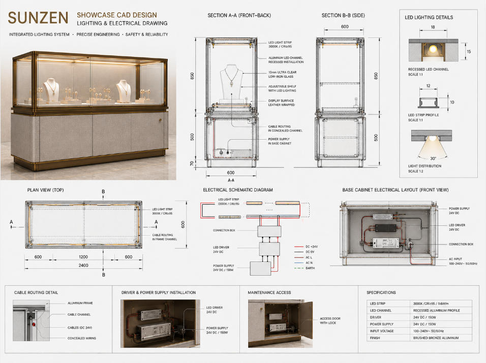
3D Showcase Design and CAD Drawings Have Different Roles
Communicate Appearance and Design Intent
3D visualization helps evaluate form, proportions, materials, lighting and the relationship between the showcase and its surrounding environment.
For the earlier design stage, explore custom showcase design.
Communicate Dimensions and Construction
CAD documentation defines the geometry, sections, details, materials, hardware and technical relationships required to move the approved design toward manufacturing.
Our Showcase CAD Design Workflow
Design Review
Review the approved 3D model, overall dimensions, materials and functional requirements.
Base Drawings
Develop principal elevations, plan views and overall dimensional relationships.
Section Development
Create sections through critical areas to resolve internal construction and component relationships.
Detail Development
Define glass connections, frames, lighting, hardware, shelves, doors, drawers and other critical interfaces.
Technical Review
Check dimensions, clearances, component relationships and manufacturing requirements before release.
Production Release
Issue the approved drawing information for fabrication, assembly and production control.
From General Arrangement to Construction Detail
General Arrangement Drawings
Show overall size, primary elevations, footprint and the main relationship between showcase components.
Section & Component Drawings
Explain internal construction, component dimensions, hardware locations and functional relationships.
Enlarged Construction Details
Focus on critical interfaces where precise fabrication or assembly information is required.
CAD Documentation for Different Display Case Types
Jewelry Showcase CAD Drawings
Coordinate glass, secure openings, drawers, locks, lighting and refined customer-facing details.
Explore our jewelry display cases.
Watch Showcase CAD Drawings
Resolve product presentation, lighting, glass, premium material interfaces and staff-side operation.
Explore our watch display cases.
Museum Display Case CAD Drawings
Document larger glazing systems, access methods, internal display volumes and exhibition-specific construction.
Explore our museum display cases.
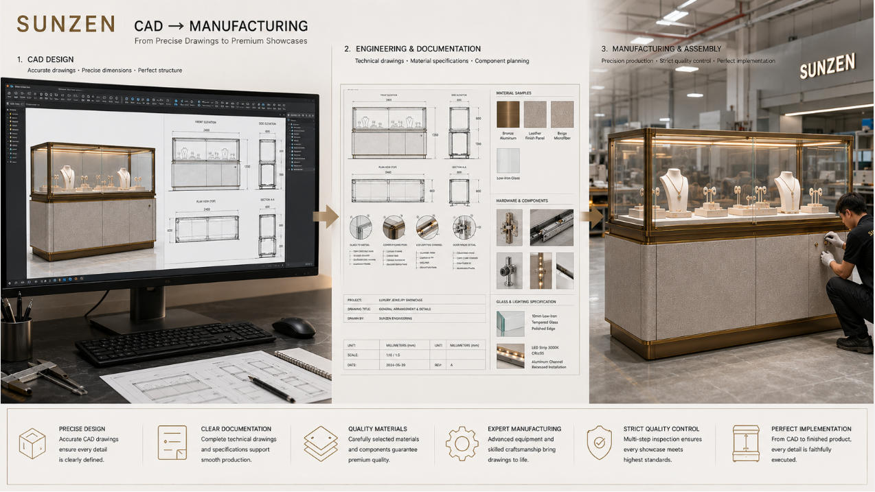
Use CAD Drawings as the Link Between Engineering and Manufacturing
The value of a technical drawing becomes clear when the information can be used consistently by engineering, fabrication, assembly and quality-control teams.
SUNZEN connects CAD development with display case engineering and showcase manufacturing, helping reduce the gap between an approved visual concept and the finished physical showcase.
For projects requiring coordination beyond factory production, our project delivery capability supports the next stage from packing and shipping to installation-stage coordination.
Why Detailed CAD Documentation Matters
Reduce Ambiguity
Clear dimensions, sections and details reduce reliance on assumptions during fabrication and assembly.
Coordinate Components
Glass, metal, cabinetry, lighting and hardware can be reviewed together before individual components enter production.
Maintain Design Intent
Technical documentation helps preserve approved proportions, details and functional relationships as the project moves into manufacturing.
Showcase CAD Design FAQs
What is showcase CAD design?
Showcase CAD design is the technical drawing stage that translates an approved display concept into precise plans, elevations, sections, dimensions and construction details for engineering and manufacturing.
What drawings are normally included in a showcase CAD drawing set?
A showcase CAD drawing set can include front and side elevations, plan views, sections, overall dimensions, component dimensions, construction details, glass information, hardware positions, lighting details and assembly relationships.
What is the difference between 3D showcase design and CAD design?
3D showcase design primarily communicates appearance, proportions, materials and visual intent. CAD design communicates accurate dimensions, construction, sections, details and technical relationships required for manufacturing.
Why are section drawings important for display cases?
Section drawings reveal internal construction that cannot be clearly understood from external elevations, including glass supports, frames, lighting channels, hardware, shelves and cabinet structure.
Can CAD drawings show showcase hardware and opening systems?
Yes. CAD drawings can document hinges, sliding systems, drawers, locks, opening directions, travel distances and clearances so moving components can be coordinated before production.
Can lighting be included in showcase CAD drawings?
Yes. Technical drawings can show LED profiles, lighting channels, cable routes, driver locations and maintenance access in relation to the physical construction of the showcase.
Are showcase CAD drawings used for manufacturing?
Yes. Approved technical drawings provide manufacturing and assembly teams with dimensional and construction information that helps translate the showcase design into physical components.
Can SUNZEN provide CAD design and manufacture the same showcase?
Yes. SUNZEN connects showcase CAD design with engineering, custom manufacturing, quality control and project delivery, allowing approved technical documentation to move directly toward production.
Need Production-Ready CAD Drawings for Your Showcase?
Share your approved concept, 3D design, dimensions, materials and functional requirements with SUNZEN. Our team can develop detailed showcase CAD drawings and coordinate them with engineering and manufacturing requirements.